
From Rust Staining to Severe Corrosion: Reading Three Field Images
Three field photographs show localized coating loss and exposed, corroded steel beside a largely coated vessel. This case study separates visible evidence from possible causes and sets out what to verify before recoating.
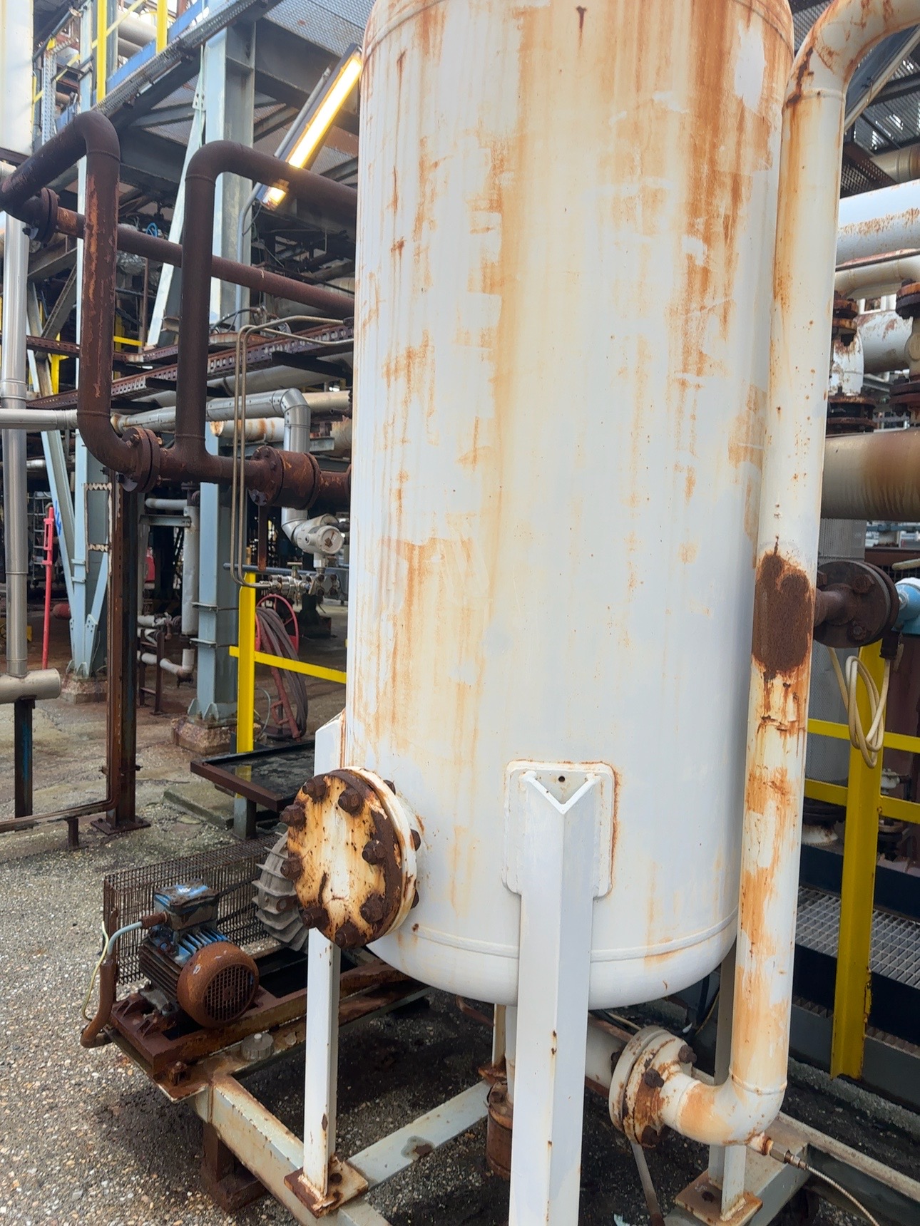
Adjacent surfaces in an industrial unit do not necessarily deteriorate at the same rate. In these photographs, much of the vessel's white coating remains, while a nearby pipe has a large area of coating loss. The first question is not which paint to apply. It is what has failed, and whether the metal itself needs an integrity assessment.
What the overview shows
The cover photograph shows rust staining on parts of the vessel and a much darker, more severely affected area on the pipe to its right. That contrast is observable; its cause is not. The line's service, temperature, coating history, and local wetting conditions have not been established. Rust staining on an apparently intact film, localized coating breakdown, and corrosion of exposed steel are different conditions and should be recorded separately.
The boundary between intact and failed coating
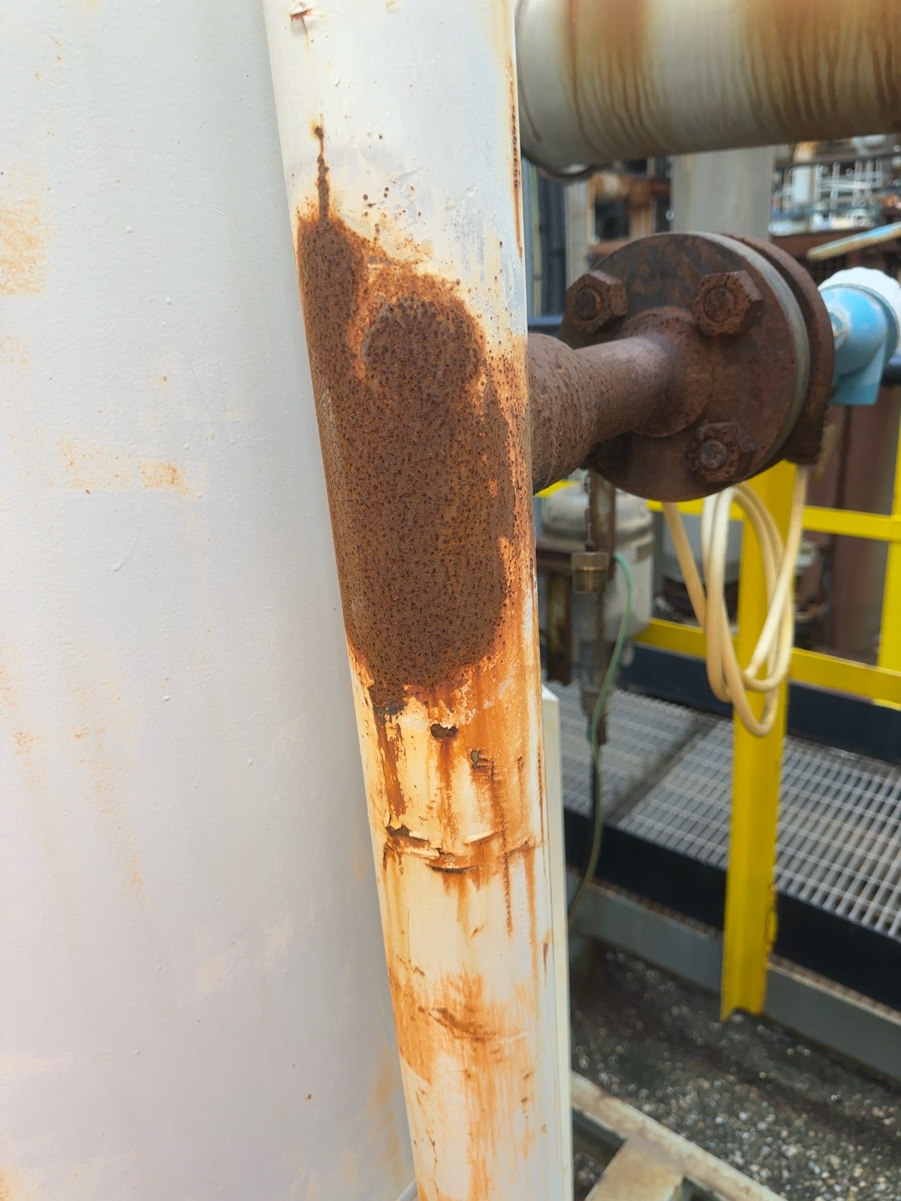
Figure 2. The main area of coating loss, with remaining white coating and an adjacent flange.
The second image makes the boundary of the affected area clearer. This is more than a superficial stain: the protective film is absent across a substantial part of the pipe. The pattern may be consistent with local initiation followed by corrosion and underfilm spread, but a photograph cannot prove that sequence. The connection geometry and possible water run-off are useful inspection leads, not confirmed root causes.
What the close-up warns us about
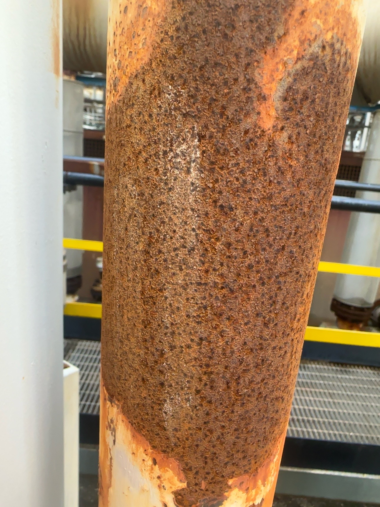
Figure 3. Rough exposed metal and visible depressions. Open the image for a closer view.
The exposed surface is rough and uneven, with visible depressions. Localized surface attack and possible pitting therefore warrant investigation. Neither pit depth nor remaining wall thickness can be measured from this image. If this is a pressure-containing process line, recoating before the necessary inspection could conceal evidence relevant to its integrity.
Why might neighboring surfaces differ?
Potential contributors include coating type and age, original surface preparation, operating temperature and cycling, condensation, time of wetness, run-off, localized contamination, connection geometry, and maintenance damage. The photographs do not confirm any one of these explanations. A defensible report should state that different degrees of deterioration were observed, then list the possible causes for field verification.
A practical assessment sequence
- Record the extent of damage, the coating boundary, nearby connections, and possible water-entry or retention points.
- Review available drawings and records for line service, material, nominal thickness, existing coating system, and repair history. Mark unavailable information as unknown.
- Plan cleaning and surface preparation against the project specification and selected repair system. Reassess the substrate after failed coating and loose corrosion products have been removed; do not assign a rust grade or preparation grade solely from these photographs.
- Where deep pitting or wall loss is suspected, refer the area to inspection or integrity specialists before coating. Thickness measurements and further assessment may be needed.
- Decide on repair extent, surface preparation, coating system, and acceptance criteria only after the condition of the metal has been evaluated.
The lesson from this case
These images are useful for learning to distinguish rust staining, coating breakdown, and corrosion of exposed metal. They cannot replace measurements or equipment records. A careful preliminary statement is: “Severe localized corrosion with coating breakdown is visible; suspected pitting or wall loss requires field verification.”
Further reading: API 570's scope for in-service piping inspection and ISO 8501-1 on visual assessment of steel surfaces. Project-specific documents remain decisive.